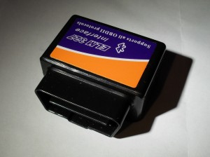
The ELM327 is a popular IC developed by Elm Electronics for communicating with the standard OBDII (On Board Diagnostics) protocols through the OBD2 port on your vehicle. This is used by mechanics and DIY’ers to diagnose and troubleshoot vehicle problems. It is also used by enthusiasts for getting useful information about your vehicle in real-time, such as speed, revs, temperature, air-flow, fuel consumption, etc.
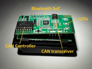
I purchased one of these adapters from dx.com (SKU: 126921) , only to realise my mistake later that the adapters sold from China are nearly all counterfeit clones of the original ELM327 by Elm Electronics, and many of them do not work. Taking a look inside the adapter you can see some problems straight away.
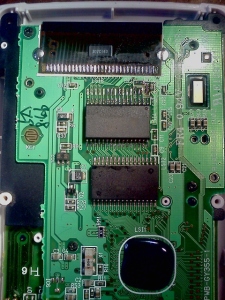
The inside contains two layers. The top layer has a Beken BK3231 Bluetooth SoC, a Microchip MCP2515 CAN Controller, and a NXP TJA1050 CAN transceiver. There are also three status LED’s which are not visible from the outside. My guess here, is that this design is the same internally as some of the transparent designs sold on the same website which have status LED’s visible. By using different cases, some more closely resembling an official product, they can sell more.
The bottom layer is concerning. There are two voltage regulators and solder joints to the ODB2 pins. Only pins 4,5, 6, 7, 14, 15, and 16 are soldered to the bottom board. Pins 1, 2, 3, 8, 9, 10, 11, 12, and 13 are unconnected. The adapter advertises that “All OBDII protocols are supported”. However this is impossible, as pin 2 is required for the Bus Positive Line of SAE J1850 PWM and VPW, while pin 10 is required for the Bus Negative Line of SAE J1850 PWM.
What about the top board? Well the thing about the genuine ELM327 adapter is that it uses a PIC microcontroller, on which the ELM327 firmware is loaded. Nowhere on this adapter is such a PIC microcontoller. In fact, the only IC capable of running code on this adapter is the Beken Bluetooth SoC. According to the Beken datasheet, this SoC has 256 KiB of flash memory, and uses an ARM 968E-S core. This is incompatible with the PIC instruction set. So just what has happened here?
I have to make some guesses about the history of fake ELM327 adapters. Supposedly, the original ELM327 v1.0 did not contain copy protection, and the firmware was cloned in China. The firmware version was changed to report v1.5, and a large number of these fake adapters were made from the pirated ELM327 v1.0 firmware. Keep in mind that Elm Electronics never released a version 1.5 firmware of ELM327. Thus all v1.5 adapters are fake.
However, the version reported on the packaging of my adapter states v1.5, but there is no PIC microcontroller inside. How can this adapter be a clone of the original v1.0 ELM327 firmware?
Perhaps the makers of these fake adapters wanted to save costs by not having to include a PIC microcontroller inside the adapter as well as a Bluetooth controller. Instead they use the Bluetooth controller to run the ELM327 code so they can save cost. The problem is that the ELM327 firmware is written for a PIC microcontoller, and not an ARM CPU, which is what you will find inside Bluetooth SoC devices. It is not easy to re-use the PIC microcode unless you can emulate the PIC on the ARM.
I guess that the ELM327 firmware had to be re-written, from scratch, perhaps with reference and help from the original PIC microcode. This is no easy task,and it doesn’t seem like they did it correctly. When they finally finished the new “fake” ARM ELM327 firmware, they gave it firmware version 2.1 to keep in line with the latest genuine version from Elm Electronics. The new fake ELM327 v2.1 adapters sold quite well, but there was a problem; there are bugs, and the support of the ELM327 command set is even worse than that of the original v1.0. Word spread around that the v2.1 adapters from China don’t work. To solve this problem they changed the version number back to v1.5. The original clone from China had v1.5 reported, and used a PIC microcontroller, and had full support of the ELM327 v1.0 command set. But this new version only has partial support – as it is a buggy and incomplete re-write of the genuine PIC firmware. The result is that it’s now really hard to tell whether an adapter that states v1.5 firmware is really the original PIC cloned firmware, or the new buggy and incomplete re-write.
To confirm some of this, I connected with Bluetooth to the adapter, and used a terminal application to try out some of the ELM327 command set that should be supported by v1.0 firmware.
>ATZ
ELM327 v1.5
>ATSP5
OK
>ATE0
OK
>ATS0
?
>ATAT1
?
>ATSTT3A
?
>ATAL
?
The fake ELM327 adapter does not even support all the basic commands of the ELM327 v1.0 command set. The ATZ command resets the device, which worked OK, but the ATAL command – to allow long byte messages – failed to be recognized. As did a number of other commands.
This adapter failed completely in my car, even though it has the pins needed for ISO 14230-4 fast-init protocol soldered on the adapter.
I tried a number of android and PC ELM327 reader applications without success.
